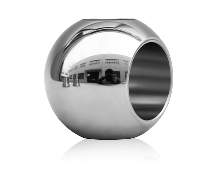
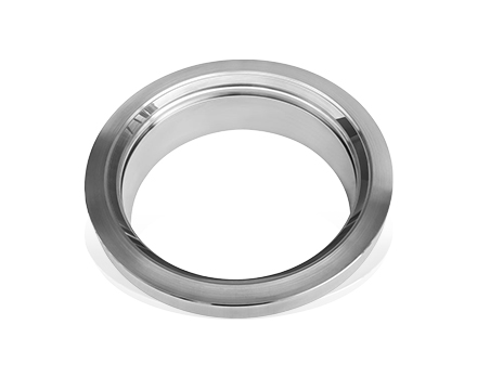
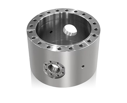
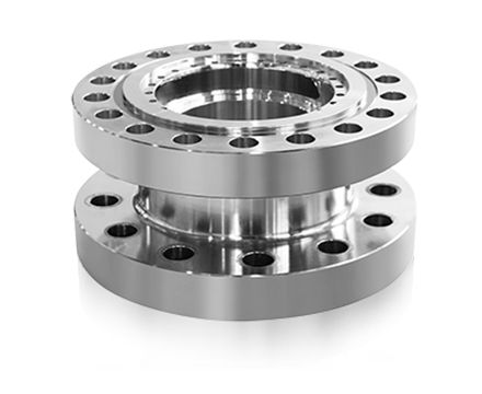
A pipeline isolation valve may remain open for months while oil or natural gas moves through the system. Yet when a leak, abnormal pressure condition, or equipment failure occurs, that same valve may need to close without delay. A Trunnion Type Ball Valve is commonly considered for this duty because its supported ball structure is suitable for automated operation in demanding pipeline conditions. When fitted with a compatible actuator and connected to an Emergency Shutdown (ESD) system, it can isolate a pipeline section in response to a predefined safety command.
For operators in the oil and gas industry, choosing the valve is only part of the job. The actuator must have enough force to move it, the control circuit must deliver the correct signal, and the valve must reach the position required by the process design. A problem with any of these elements can affect the shutdown function.
Understanding the Valve's Position in an ESD System
An ESD system is designed to protect people, equipment, and process facilities when operating conditions become unsafe. In a gas transmission station, for example, an abnormal pressure condition may require the isolation of a pipeline section. At a refinery, a process disturbance may require a particular unit to be separated from its connected equipment.
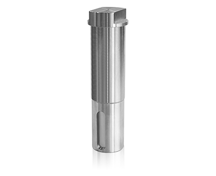
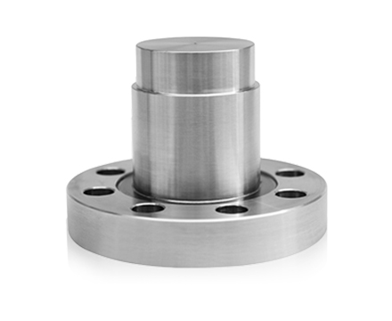
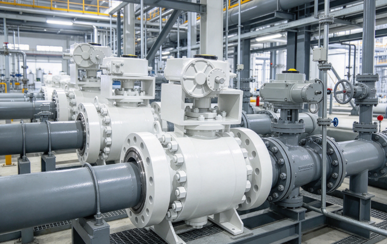
The Trunnion Type Ball Valve provides the mechanical isolation. Its ball is supported by upper and lower trunnions, allowing it to rotate while remaining supported under pipeline pressure. The actuator transfers movement through the valve stem, turning the ball between its open and closed positions.
In an automated installation, the valve receives its operating command from the shutdown control arrangement rather than depending on an operator to turn a handwheel.
This makes the valve relevant to applications such as:
- Natural gas transmission and compressor stations.
- Crude oil transfer and storage facilities.
- Offshore production installations.
- Refinery and petrochemical process lines.
- Industrial pipelines carrying hazardous fluids.
The required valve position is determined by the process safety design. Closing the valve may be necessary to stop the supply of a hazardous medium, while some applications require another response to protect connected equipment.
Why Does the Trunnion Structure Matter in Pipeline Isolation?
The way a ball is supported affects how a valve behaves under pressure.
In a floating ball design, pipeline pressure pushes the ball against the downstream seat. A trunnion-mounted ball is held by fixed support points, limiting its movement during operation. This arrangement helps manage the mechanical loads acting on the ball and seats.
For automated pipeline isolation, several characteristics are worth considering.
- Supported ball construction: The trunnions help maintain ball alignment under pressure. This is relevant where the valve operates under changing pipeline conditions.
- Operating torque: The supported arrangement can reduce pressure-related ball movement. However, the actual torque still depends on the valve size, pressure differential, seat design, and service medium.
- Sealing arrangement: Depending on the internal design, a valve can provide isolation from either flow direction. Engineers should confirm the specified seat configuration rather than assume all models have identical sealing capabilities.
- Material selection: Body, ball, and seat materials need to suit the transported medium and operating temperature. Natural gas, crude oil, and chemical process fluids may require different material combinations.
- Fire-safe construction: Where fire exposure is identified as a project hazard, an applicable fire-tested design may be specified to maintain defined sealing performance during and after testing.
These features explain why trunnion-mounted designs are frequently considered for pipeline duties. They do not remove the need for proper valve sizing, actuator selection, and installation review.
The Equipment Behind an Automated Shutdown Valve
A shutdown valve is a complete assembly rather than a standalone mechanical component. Its operation depends on the control equipment and power supply connected to it.
| Equipment |
Purpose |
| Trunnion Type Ball Valve |
Blocks the pipeline flow |
| Pneumatic Actuator |
Uses compressed air or gas to operate the valve |
| Hydraulic Actuator |
Uses hydraulic pressure to generate movement |
| Solenoid Valve |
Controls the actuator supply circuit |
| Safety PLC |
Processes shutdown signals |
| Pressure Transmitter |
Monitors pipeline pressure |
| Limit Switch |
Indicates the valve's position |
| Instrument Air Supply |
Provides pneumatic operating power |
The actuator is mounted onto the valve through a suitable mechanical interface. Its output torque must be sufficient for the valve to operate under the specified service conditions.
The solenoid valve connects the electrical control signal with the pneumatic or hydraulic circuit. When a shutdown command is issued, it changes the actuator supply arrangement according to the system design.
Limit switches provide position feedback. If the control room receives a close command but the valve does not reach its closed position, the feedback signal can help operators identify the discrepancy.
For remote pipeline stations, this information is particularly useful because the valve may be located far from the operating personnel.
How Does the ESD Sequence Move the Valve?
Consider a gas transmission pipeline where a pressure transmitter detects a condition outside the permitted operating range. The ESD system evaluates the signal and, when the shutdown criteria are met, initiates the required isolation action.
The sequence normally involves several connected operations.
- Detection: Field instruments or approved emergency devices identify the abnormal condition.
- Logic processing: The Safety PLC evaluates the input against the configured shutdown logic.
- Output signal: The controller sends a command to the solenoid valve.
- Actuator movement: The actuator transfers torque through the valve stem.
- Isolation: The ball rotates into the required position and blocks the flow passage.
- Feedback: Position switches report the valve's actual condition to the control system.
The sequence needs to be considered as a complete operating function. A controller can issue a shutdown command, but the pipeline will not be isolated unless the solenoid circuit and actuator operate correctly and the valve completes its movement.
The required response during loss of power or operating pressure also needs to be established in advance. A fail-close arrangement may be suitable for one gas supply line, while another process may require fail-open or a different predefined position. The decision should follow the process hazard assessment.
Selecting an Actuator for the Required Fail-safe Action
Pneumatic and hydraulic actuators are both used in oil and gas installations. Their suitability depends on the operating environment, available utilities, valve torque, and required response.
| Consideration |
Pneumatic Actuator |
Hydraulic Actuator |
| Power source |
Compressed air or gas |
Hydraulic fluid |
| Supporting equipment |
Air supply and control circuit |
Hydraulic power unit |
| Maintenance |
Seals, tubing, and accessories |
Seals, fluid, and hydraulic connections |
| Design consideration |
Supply pressure and air quality |
Fluid condition and pressure availability |
Spring-return actuators use stored mechanical energy to move the valve toward a designated position when the operating supply is lost. Double-acting actuators use powered movement in both directions and require a suitable arrangement for the specified failure condition.
Valve torque information should be obtained before selecting the actuator. Breakaway torque, running torque, seating torque, and the maximum differential pressure all need consideration.
An actuator selected only by matching its nominal size to the valve diameter may not provide sufficient operating force. The final selection should be supported by the manufacturer's torque data and sizing documentation.
Safety Standards and Requirements for ESD Valve Assemblies
A pipeline shutdown valve is part of a wider safety arrangement. Its technical requirements should be considered alongside the control system, instrumentation, actuator, and maintenance plan.
| Standard |
Main Application |
| IEC 61508 |
Functional safety |
| IEC 61511 |
Safety instrumented systems in process industries |
| API 6D |
Pipeline valve design and testing |
| API 607 |
Fire testing for applicable valve designs |
| API 6FA |
Fire testing requirements |
| ISO 5211 |
Valve and actuator mounting interfaces |
| ISO 15848 |
Fugitive emission testing |
SIL requirements apply to the complete Safety Instrumented Function, not simply to the ball valve. The valve may form part of the final element subsystem, but its contribution must be evaluated together with the actuator, control arrangements, and supporting equipment.
Fire-safe requirements also deserve attention in hydrocarbon service. Engineers should check the applicable test standard, product documentation, and project acceptance criteria rather than relying solely on a general fire-safe description.
Testing and Maintenance in Operating Pipeline Facilities
One challenge with emergency shutdown valves is that they may remain in the same position throughout normal production. A valve that has not moved for an extended period still needs to respond when an emergency occurs.
Maintenance should cover the valve, actuator, and control accessories.
- Functional testing: Verify that the shutdown command produces the required actuator and valve movement.
- Partial Stroke Testing: Check a defined portion of valve travel to identify certain potential mechanical problems. This does not replace full proof testing.
- Seat leakage inspection: Verify isolation performance against the applicable acceptance criteria.
- Actuator inspection: Examine seals, air connections, hydraulic lines, and mounting components.
- Position feedback testing: Confirm that limit switch indications correspond to the actual valve position.
Testing procedures and intervals should follow the project's safety lifecycle requirements. Inspection records should also identify any changes to the valve assembly or control configuration.
Applications Across Oil, Gas, and Industrial Pipelines
The requirements for an automated isolation valve vary with the installation.
Gas transmission pipelines use sectionalizing valves to isolate designated pipeline sections. Actuator supply reliability and remote position monitoring are important considerations.
Oil production facilities may use trunnion-mounted valves on production lines, separators, and transfer connections. Material compatibility becomes particularly important when the transported fluid contains gas, water, and liquid hydrocarbons.
Refineries and petrochemical plants require isolation arrangements for interconnected process units. Pressure, temperature, and chemical compatibility influence the valve and seat selection.
Offshore platforms present additional installation concerns, including corrosion protection, enclosure requirements, limited maintenance access, and remote operation.
Industrial process pipelines may also use automated trunnion ball valves where a defined shutdown action is needed to protect equipment and personnel.
What Should Be Included in the Valve Selection Specification?
A clear technical specification helps the manufacturer understand the actual operating conditions and prepare a suitable valve and actuator arrangement.
| Parameter |
Information Required |
| Service medium |
Natural gas, crude oil, or process fluid |
| Valve size |
Nominal pipeline diameter |
| Pressure rating |
Design and operating pressure |
| Temperature |
Normal and abnormal service conditions |
| Body material |
Compatibility with the process medium |
| Seat material |
Sealing and temperature requirements |
| Bore design |
Full bore or reduced bore |
| Actuator type |
Pneumatic or hydraulic |
| Failure position |
Fail-close, fail-open, or specified alternative |
| Inspection requirements |
Pressure, leakage, and applicable fire testing |
Manufacturing documentation should include relevant material records, inspection reports, pressure test results, and actuator sizing information.
For an ESD application, engineers should also review the mounting interface, solenoid valve arrangement, position feedback, and required operating time.
When requesting a Trunnion Type Ball Valve for an oil or gas pipeline project, providing the process medium, valve size, pressure class, temperature range, actuator preference, and required failure position gives the manufacturer the information needed to assess the proposed configuration.

 English
 中文简体
 русский
 Español
 عربى
 italiano