In most automated pipeline setups, valve movement is not treated as a standalone action. It is usually part of a wider loop where signals go out, something moves, and a confirmation comes back. In the field, Ball Valve Accessories are the parts that quietly sit in between the valve and the control side, making that loop actually workable.
On paper the system looks clean. On site it is rarely that neat. Cable routing, air quality, bracket alignment, and even small vibration from nearby equipment can all affect how the valve behaves. These accessories are basically what keep things from becoming inconsistent after installation.
What Ball Valve Accessories Include in Industrial Automation Systems
In actual projects, the configuration depends more on how the line is operated than any fixed design idea. You usually see a few functional pieces coming together rather than a complete "package" that looks identical everywhere.
In many installations, the setup is built around:
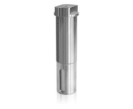
- A driving unit that physically moves the valve
- A position check device that confirms open or close state
- A mechanical interface that links actuator and valve stem
Sometimes there is also a small air preparation unit in pneumatic setups. This is not always given much attention during design, but in the field it often becomes important when air quality is not stable. If moisture or pressure fluctuation appears, the movement can feel less consistent than expected.
Not every system uses all of these, and in retrofit work you often see partial combinations depending on what was already installed.
How Ball Valve Actuators Are Selected Based on Torque and Operating Conditions
Actuator selection in real projects is rarely a clean calculation exercise. Engineers usually start with valve size and expected resistance, but the final decision often comes after considering how the system actually behaves during operation.
For example, two valves of the same size may not need the same driving force if one is handling clean fluid and the other is dealing with heavier or sticky media. That difference only becomes obvious after experience with similar lines or after commissioning feedback.
| Operating situation |
What is usually considered |
| smoother flow conditions |
lighter driving requirement |
| mixed or variable flow |
balanced response behavior |
| higher resistance flow |
stronger actuation margin |
In field work, adjustments are common after startup. Sometimes the actuator is kept, sometimes it is changed, and sometimes air settings are tuned instead of replacing hardware.
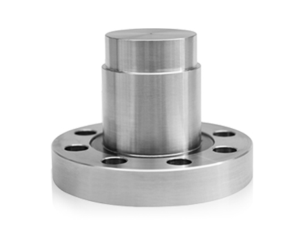
How ISO 5211 Mounting Standard Supports Ball Valve Accessories Installation Compatibility
Mechanical connection between actuator and valve is one of those points that looks simple until installation begins. Even when parts are designed to match a standard interface, small alignment issues can show up on site.
The ISO 5211 mounting pattern helps reduce guesswork during assembly. It gives a shared hole layout and coupling approach, so different components can be connected without redesigning everything from scratch.
In practice though, engineers still pay attention to:
- Whether the bracket sits flat without stress
- If the coupling engages smoothly without tight spots
- How the assembly behaves after tightening, not just before
Small deviations here can show up later as uneven movement or slight delay in response. This is usually noticed during testing rather than design.
Which Position Feedback Solutions Are Used for Accurate Ball Valve Control
Position feedback is one of those things that only gets noticed when it is not reliable. In the field, it is used to confirm whether the valve actually reached the expected state, not just whether a command was sent.
Depending on how the system is built, different approaches are used. Simple mechanical switches are still common in basic setups where only open and close confirmation is needed. In more integrated systems, sensor-based signals are used so the control room can see more detail about movement behavior.
In many real installations, both types end up being used together. One gives a basic status signal, and the other provides more refined feedback for control adjustments. This combination is often chosen because it is easier to maintain during long-term operation.
How Smart Positioners Improve Control Accuracy in Ball Valve Automation Applications
In the field, a smart positioner is often less about "advanced features" and more about keeping the valve behavior steady when the line does not stay perfectly steady. Pressure changes, load variation, and small mechanical differences can all show up during normal operation. A positioner helps reduce that gap between the control signal and the actual valve movement.
What matters most is not the label on the device, but how it behaves after installation. A system may look fine during bench testing and still drift a little once it is mounted, wired, and exposed to real conditions. That is usually where a positioner becomes useful. It keeps the movement closer to what the control system expects, especially when the valve is used repeatedly over long periods.
In practice, engineers often pay attention to a few things:
- How smoothly the valve reacts to small command changes
- Whether the output settles without unnecessary hunting
- How stable the signal remains when the line conditions shift
When those points are handled well, the valve tends to behave in a more predictable way. That is especially important in automated lines where small movement errors can become visible in the process.
When Ball Valve Accessories Need Maintenance for Stable Operation in Process Systems
Maintenance is usually not triggered by a single failure. In many plants, people notice small changes first. The valve may move a little slower, the signal may not return as cleanly, or the actuator may sound different during operation. These signs do not always point to a major issue, but they usually mean the system should be checked before the problem grows.
A practical maintenance check often starts with the parts that move, seal, or send feedback. In some cases, the issue is mechanical wear. In others, it is air quality, loose wiring, or a bracket that has shifted slightly over time.
| Field sign |
What it often suggests |
| slower response than usual |
friction or supply side variation |
| unclear position feedback |
switch or sensor alignment issue |
| movement that feels uneven |
mounting or linkage check needed |
| repeated small delays |
air supply or internal wear may be involved |
In day-to-day work, maintenance is usually about keeping the system stable, not waiting for a visible breakdown. That is why small changes are often taken seriously. A valve assembly that looks acceptable during inspection can still behave differently after repeated cycling, especially in lines that run for long periods without interruption.
Where Ball Valve Accessories Are Applied Across Water Oil Gas and Chemical Systems
These components show up in many different systems, but the way they are used is not exactly the same. A water line and a chemical line may both need automated valve movement, yet the surrounding conditions can be very different. That changes how the accessories are arranged and what kind of support they need.
In water service, the focus is often on steady operation and straightforward control. In oil and gas environments, the installation may need to handle tougher service conditions and more attention to mechanical reliability. Chemical systems can bring their own concerns, especially where the medium may affect seals, surfaces, or surrounding parts. The same basic valve accessory set can still be used, but the details matter more than the general idea.
In field projects, the location of use often shapes the setup more than the equipment catalog does. Some systems are built for continuous duty. Others only need periodic movement. Some are kept simple so they can be maintained easily, while others use more feedback because the process depends on tighter control. That is why the same accessory family can appear in very different forms across industries.
When people ask where these parts are applied, the practical answer is usually broader than one type of plant. They are used wherever the valve needs to move under control and send a clear status back to the system. In that sense, the application is not limited to one sector. It follows the need for controlled flow, repeatable action, and dependable feedback.
 English
 中文简体
中文简体
 русский
 Español
 عربى
عربى
 italiano