Inside fluid control equipment, movement does not happen in isolation. A small rotating shaft inside the valve body carries the input force and passes it toward the internal closing element. That transfer sounds simple, but in practice it depends on how surfaces interact, how pressure behaves around the sealing zone, and how motion repeats over time.
When the system is put into long operation cycles, the behavior slowly shifts. Not in a dramatic way. More like small changes that accumulate in contact points, especially around the central rotating structure. Operators often notice it first through hand feel or resistance change rather than visible damage.
What causes Ball Valve Stem torque to increase after extended industrial operation cycles
Torque growth is usually not tied to one clear reason. It tends to appear as a combined result of surface interaction and repeated movement.
In many cases, the internal contact areas begin to adjust themselves after long use. The material does not stay in its original condition. It adapts slightly to movement paths and pressure contact zones.
A few typical influences are often observed:
- Slight increase in friction where motion is repeated most frequently
- Packing material slowly tightening under continuous compression
- Tiny particles entering contact areas during fluid flow
- Surface polish gradually changing into uneven micro-contact
A Ball Valve Stem can still rotate normally during this phase, but the required input force becomes less predictable. Sometimes the change is gradual enough that it is only noticed during routine operation checks.
Torque behavior in this context is not isolated. It reflects what is happening inside multiple layers of contact at the same time.
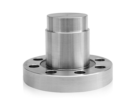
How does Ball Valve Stem transmit torque and what happens when alignment changes over time
Force transmission begins at the external driving point and moves through the shaft into the internal rotating component. Ideally, the path is straight and balanced. In real conditions, that balance can shift slightly.
Alignment changes are not always visible. They may come from repeated loading, installation variation, or small deformation under pressure cycles.
When alignment shifts, the internal motion pattern changes in subtle ways:
- One side of the contact surface carries more load than the opposite side
- Rotation may feel slightly uneven at certain angles
- Wear marks appear in a non-uniform distribution
- Motion feedback becomes less consistent across cycles
A Ball Valve Stem under these conditions does not immediately lose function. The system continues to operate, but internal contact points begin to redistribute stress.
Over time, this redistribution can affect how smoothly torque is transferred, especially during partial opening or closing positions.
Where manufacturing tolerances of Ball Valve Stem influence sealing performance in practical use
Dimensional variation plays a quiet but constant role in system behavior. Even small differences in geometry can influence how pressure is shared between contact surfaces.
In field conditions, this influence is often noticed indirectly rather than measured directly.
| Structural area |
Role during operation |
Practical influence |
| Shaft body section |
Carries rotational motion |
Affects smoothness of movement |
| Sealing contact zone |
Maintains pressure barrier |
Changes compression balance under load |
| Connection interface |
Transfers input force |
Alters load distribution during rotation |
When these areas do not match the expected fit closely, sealing behavior may shift slightly during pressure changes. The effect is not immediate failure, but a gradual change in how stable the sealing interface feels during operation.
In many cases, the system adapts to these small variations, which makes the change harder to detect in early stages.
Why Ball Valve Stem packing areas become a key point for leakage under changing pressure conditions
The packing section around the shaft is designed to manage two functions at the same time. It must allow movement while also holding pressure. These two requirements always stay in tension with each other.
During repeated operation, the packing material is exposed to continuous compression and release. It does not return to its original shape in a perfect way. Instead, it adjusts slowly.
Common conditions that influence this region include:
- Gradual reduction in elasticity of packing material
- Heat generated by repeated motion
- Slight unevenness at the contact surface
- Pressure variation during opening and closing cycles
A Ball Valve Stem system often shows its earliest leakage signs in this area because it is the only zone combining movement and sealing pressure simultaneously.
Leakage behavior is usually not sudden. It starts as minor changes in sealing tightness and becomes more noticeable under pressure variation or frequent cycling.
Which material choices for Ball Valve Stem affect performance in corrosive and high pressure environments
Material behavior in real operation is rarely visible at the beginning. A shaft can look stable during installation and still respond differently once it is exposed to continuous flow conditions. The change is usually slow enough that it blends into normal operation noise.
In corrosive media, surface condition becomes more important than bulk strength alone. Small surface reactions tend to appear first, especially where fluid movement is uneven or where contact pressure is slightly higher.
Different material behaviors can be observed in practice:
- Stainless based structures often maintain surface consistency in less reactive environments
- Alloy variations tend to respond differently when pressure and chemical exposure overlap
- Surface modified layers delay direct contact change, though their behavior depends on coating stability
- Mixed interface designs sometimes shift wear patterns toward connection zones
A Ball Valve Stem in long service does not fail by a single mechanism. Instead, it moves through gradual surface adaptation, where both pressure and chemical exposure influence the same contact areas.
Selection in engineering practice is often less about ideal performance and more about how predictable the surface remains over time.
How surface treatment on Ball Valve Stem changes friction behavior and operational stability
Surface treatment changes how two solid surfaces interact during motion. The core structure remains unchanged, but the outer layer behaves differently when contact starts repeating.
At early stages, the movement usually feels smoother. The contact resistance is reduced, and rotation requires less variation in input force. This condition, however, does not remain static.
Over repeated cycles, the treated layer begins to adjust. The change is not uniform across the surface. Some zones remain stable longer, while others shift earlier due to contact concentration.
Common observed patterns include:
- Reduced friction during initial operation cycles
- More consistent rotational feedback at early use stage
- Gradual surface adaptation after repeated contact
- Slight change in lubrication response depending on environment conditions
A Ball Valve Stem with surface treatment does not behave the same across its full lifecycle. The transition from stable motion to gradual resistance change is usually slow and not clearly defined at a single point.
In field conditions, this is often noticed only when operating feel becomes slightly less predictable during routine handling.
What makes Ball Valve Stem design sensitive to long term wear under repeated cycling conditions
Wear is not distributed evenly. Even when the movement looks symmetrical, internal contact points do not always share the same load. Small differences in force path create uneven surface development over time.
Repeated cycling creates a pattern rather than random wear. The same areas experience contact again and again, while other zones remain relatively stable.
Typical contributing factors include:
- Repeated loading at similar angular positions
- Slight deviation in alignment during operation cycles
- Localized pressure concentration on contact interfaces
- Gradual smoothing of originally machined surfaces
A Ball Valve Stem under long operation does not show sudden structural change. Instead, the surface slowly shifts from defined contact geometry toward more adapted contact paths.
This process can affect how rotation feels. It does not always influence function immediately, but it changes consistency across repeated operations.
Wear sensitivity is therefore more related to contact repetition than to material strength alone.
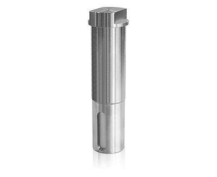
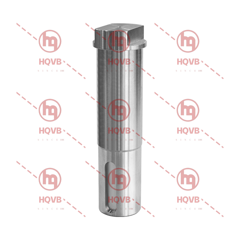
How anti blowout Ball Valve Stem structures work and why they matter in pressure safety scenarios
Anti blowout design is mainly concerned with controlling axial movement. Under pressure variation, internal force can shift direction, and without restriction, the shaft may experience unwanted displacement.
The structural idea is relatively direct, but its behavior depends on how force is distributed inside the valve body.
Key functional behaviors include:
- A retention shoulder that limits upward movement under internal pressure
- Housing geometry that keeps the shaft aligned within a controlled path
- Force distribution that redirects pressure load away from exit direction
- Clearance control that allows rotation while restricting axial travel
A Ball Valve Stem with this configuration behaves in a more constrained way when internal pressure changes. The movement is still rotational, but axial instability is reduced through structural limitation rather than external control.
In practical operation, the importance of this design becomes clearer when pressure conditions fluctuate or when system load is not steady. The structure does not eliminate force, but it prevents displacement from becoming part of the motion path.
 English
 中文简体
中文简体
 русский
 Español
 عربى
عربى
 italiano